Hi,
You might be thinking why am writing this blog even though there is plenty of information and help pages available for GMF.
I worked around 5moths using GMF, and still feel that I did not have proper ideas of how things work in GMF. I could not find any proper documentation that says what exactly the generated code does, how it works, why this code is being generated. So I am writing this blog for those who faced same situation in GMF. I will try to post as many articles as I can and explain everything I have learnt in GMF. I must say there are indeed really cool things one can do with GMF.
This documentation will have *most* part copy-pasted from other sources. I would have provided appropriate links to those sources. This is because the contents present on web requires some more detailed explanation with proper reasoning, which I did not find in most articles.
If Any reader familiar with GMF, do let me improve this blog and make a better source of learning for those using Eclipse's cool frameworks !!!
Cheers,
Amit M Surana
Friday
Thursday
Eclipse Introduction
If you are new to eclipse then go on and read this.
Eclipse is an open source software development project, the purpose of which is to provide a highly integrated tool platform. The work in Eclipse consists of a core project, which includes a generic framework for tool integration, and a Java development environment built using it. Other projects extend the core framework to support specific kinds of tools and development environments. The projects in Eclipse are implemented in Java and run on many operating systems including Windows and Linux.
By involving committed and enthusiastic developers in an environment organized to facilitate the free exchange of technology and ideas, Eclipse is hoping to create the best possible integration platform. The software produced by Eclipse is made available under the Common Public License (CPL), which contains the usual legalese, but basically says that you can use, modify, and redistribute it for free, or include it as part of a proprietary product. The CPL is Open Source Initiative (OSI)-approved and recognized by the Free Software Foundation as a free software license. Any software contributed to Eclipse must also be licensed under the CPL.
Eclipse.org is a consortium of a number of companies that have made a commitment to provide substantial support to the Eclipse project in terms of time, expertise, technology, or knowledge. The projects within Eclipse operate under a clearly defined charter that outlines the roles and responsibilities of the various participants including the board, Eclipse users, developers, and the project management committees.
![]() It is built to meet the following requirements:
It is built to meet the following requirements:
- Support the construction of a variety of tools for application development.
- Support an unrestricted set of tool providers, including independent software vendors (ISVs).
- Support tools to manipulate arbitrary content types (e.g., HTML, Java, C, JSP, EJB, XML, and GIF).
- Facilitate seamless integration of tools within and across different content types and tool providers.
- Support both GUI and non-GUI-based application development environments.
- Run on a wide range of operating systems, including Windows® and Linux.
- Capitalize on the popularity of the Java programming language for writing tools.
Eclipse Plug-in Development Environment
 An Eclipse plug-in is the smallest unit of Eclipse Platform function that can be developed and delivered separately. Usually a small tool is written as a single plug-in, whereas a complex tool has its functionality split across several plug-ins. Except for a small kernel known as the Platform Runtime, all of the Eclipse Platform's functionality is located in plug-ins.
Eclipse Plug-ins are coded in Java. A typical plug-in consists of Java code in a JAR library, some read-only files, and other resources such as images, web templates, message catalogs, native code libraries, etc. Some plug-ins do not contain code at all. One such example is a plug-in that contributes online help in the form of HTML pages. A single plug-in's code libraries and read-only content are located together in a directory in the file system, or at a base URL on a server. There is also a mechanism that permits a plug-in to be synthesized from several separate fragments, each in their own directory or URL. This is the mechanism used to deliver separate language packs for an internationalized plug-in.
Each plug-in has a manifest file declaring its interconnections to other plug-ins. The interconnection model is simple: a plug-in declares any number of named extension points, and any number of extensions to one or more extension points in other plug-ins.
A plug-in’s extension points can be extended by other plug-ins. For example, the workbench plug-in declares an extension point for user preferences. Any plug-in can contribute its own user preferences by defining extensions to this extension point.
An extension point may have a corresponding API interface. Other plug-ins contribute implementations of this interface via extensions to this extension point. Any plug-in is free to define new extension points and to provide new API for other plug-ins to use.
On start-up, the Platform Runtime discovers the set of available plug-ins, reads their manifest files, and builds an in-memory plug-in registry. The Platform matches extension declarations by name with their corresponding extension point declarations. Any problems, such as extensions to missing extension points, are detected and logged. The resulting plug-in registry is available via the Platform API. Plug-ins cannot be added after start-up.
Plug-in manifest files contain XML. An extension point may declare additional specialized XML element types for use in the extensions. This allows the plug-in supplying the extension to communicate arbitrary information to the plug-in declaring the corresponding extension point. Moreover, manifest information is available from the plug-in registry without activating the contributing plug-in or loading of any of its code. This property is key to supporting a large base of installed plug-ins only some of which are needed in any given user session. Until a plug-in’s code is loaded, it has a negligible memory footprint and impact on start-up time. Using an XML-based plug-in manifest also makes it easier to write tools that support plug-in creation. The Plug-In Development Environment (PDE), which is included in the Eclipse SDK, is such a tool.
A plug-in is activated when its code actually needs to be run. Once activated, a plug-in uses the plug-in registry to discover and access the extensions contributed to its extension points. For example, the plug-in declaring the user preference extension point can discover all contributed user preferences and access their display names to construct a preference dialog. This can be done using only the information from the registry, without having to activate any of the contributing plug-ins.
The contributing plug-in will be activated when the user selects a preference from a list. Activating plug-ins in this manner does not happen automatically; there are a small number of API methods for explicitly activating plug-ins. Once activated, a plug-in remains active until the Platform shuts down. Each plug-in is furnished with a subdirectory in which to store plug-in-specific data; this mechanism allows a plug-in to carry over important state between runs.
The Platform Runtime declares a special extension point for applications. When an instance of the Platform is launched, the name of an application is specified via the command line; the only plug-in that gets activated initially is the one that declares that application.
By determining the set of available plug-ins up front, and by supporting a significant exchange of information between plug-ins without having to activate any of them, the Platform can provide each plug-in with a rich source of pertinent information about the context in which it is operating. This context cannot change while the Platform is running, so there is no need for complex life cycle events to inform plug-ins when the context changes. A lengthy start-up sequence is avoided, as is a common source of bugs stemming from unpredictable plug-in activation order.
The Eclipse Platform is run by a single invocation of a standard Java virtual machine. Each plug-in is assigned its own Java class loader that is solely responsible for loading its classes (and Java resource bundles). Each plug-in explicitly declares its dependence on other plug-ins from which it expects to directly access classes. A plug-in controls the visibility of the public classes and interfaces in its libraries. This information is declared in the plug-in manifest file; the visibility rules are enforced at runtime by the plug-in class loaders.
The plug-in mechanism is used to partition the Eclipse Platform itself. Indeed, separate plug-ins provides the workspace, the workbench, and so on. Even the Platform Runtime itself has its own plug-in. Non-GUI configurations of the Platform may simply omit the workbench plug-in and the other plug-ins that depend on it.
The Eclipse Platform's update manager downloads and installs new features or upgraded versions of existing features (a feature being a group of related plug-ins that get installed and updated together). The update manager constructs a new configuration of available plug-ins to be used the next time the Eclipse Platform is launched. If the result of upgrading or installing proves unsatisfactory, the user can roll back to an earlier configuration.
The Eclipse Platform Runtime also provides a mechanism for extending objects dynamically. A class that implements an “adaptable” interface declares its instances open to third party behavior extensions. An adaptable instance can be queried for the adapter object that implements an interface or class. For example, workspace resources are adaptable objects; the workbench adds adapters that provide a suitable icon and text label for a resource. Any party can add behavior to existing types (both classes and interfaces) of adaptable objects by registering a suitable adapter factory with the Platform. Multiple parties can independently extend the same adaptable objects, each for a different purpose. When an adapter for a given interface is requested, the Platform identifies and invokes the appropriate factory to create it. The mechanism uses only the Java type of the adaptable object (it does not increase the adaptable object's memory footprint). Any plug-in can exploit this mechanism to add behavior to existing adaptable objects, and to define new types of adaptable objects for other plug-ins to use and possibly extend.
Wednesday
Eclipse Modeling Framework
EMF is a Java framework and code generation facility for building tools and other applications based on a structured model. For those of you that have bought into the idea of object-oriented modeling, EMF helps you rapidly turn your models into efficient, correct, and easily customizable Java code. For those of you that aren't necessarily sold on the value of formal models, EMF is intended to provide you with the same benefits and a very low cost of entry.
So, what do we mean when we say model? When talking about modeling, we generally think about things like Class Diagrams, Collaboration Diagrams, State Diagrams, and so on. UML (Unified Modeling Language) defines a (the) standard notation for these kinds of diagrams. Using a combination of UML diagrams, a complete model of an application can be specified. This model may be used purely for documentation or, given appropriate tools, it can be used as the input from which to generate part of or, in simple cases, all of an application.
Given that this kind of modeling typically requires expensive Object Oriented Analysis and Design (OOA/D) tools, you might be questioning our assertion, above, that EMF provides a low cost of entry. The reason we can say that is because an EMF model requires just a small subset of the kinds of things that you can model in UML, specifically simple definitions of the classes and their attributes and relations, for which a full-scale graphical modeling tool is unnecessary.
While EMF uses XMI (XML Metadata Interchange) as its canonical form of a model definition, you have several ways of getting your model into that form:
- Create the XMI document directly, using an XML or text editor
- Export the XMI document from a modeling tool such as Rational Rose
- Annotate Java interfaces with model properties
- Use XML Schema to describe the form of a serialization of the model
The first approach is the most direct, but generally only appeals to XML gurus. The second choice is the most desirable if you are already using full-scale modeling tools. The third approach provides pure Java programmers a low-cost way to get the benefits of EMF and its code generator using just a basic Java development environment (for example, Eclipse's Java Development Tools). The last approach is most applicable in creating an application that must read or write a particular XML file format.
Once you specify an EMF model, the EMF generator can create a corresponding set of Java implementation classes. You can edit these generated classes to add methods and instance variables and still regenerate from the model as needed: your additions will be preserved during the regeneration. If the code you added depends on something that you changed in the model, you will still need to update the code to reflect those changes; otherwise, your code is completely unaffected by model changes and regeneration.
In addition to simply increasing your productivity, building your application using EMF provides several other benefits like model change notification, persistence support including default XMI and schema-based XML serialization, a framework for model validation, and a very efficient reflective API for manipulating EMF objects generically. Most important of all, EMF provides the foundation for interoperability with other EMF-based tools and applications.
EMF consists of two fundamental frameworks: the core framework and EMF.Edit. The core framework provides basic generation and runtime support to create Java implementation classes for a model. EMF.Edit extends and builds on the core framework, adding support for generating adapter classes that enable viewing and command-based (undoable) editing of a model, and even a basic working model editor.
Tuesday
Graphical Editing Framework
Before we go in depth with GMF there is very much need to understand the MVC architecture of GEF and the working of EMG with GEF. This will be very useful when we start with "understanding generated GMF code". For more details of EMF with GEF you can read through the IBM redbook - Eclipse Development using GEF and EMF.
I will simply copy-paste the required contents as my main intention is to explain more on GMF than GEF.
The Graphical Editing Framework allows us to easily develop graphical representations for existing models. It is possible to develop feature rich graphical editors using GEF.
All graphical visualization is done via the Draw2D framework, which is a standard 2D drawing framework based on SWT from eclipse.org. The editing possibilities of the Graphical Editing Framework allow you to build graphical editors for nearly every model. With these editors, it is possible to do simple modifications to your model, like changing element properties or complex operations like changing the structure of your model in different ways at the same
time.
All these modifications to your model can be handled in a graphical editor using
very common functions like drag and drop, copy and paste, and actions invoked
from menus or toolbars.
As GEF is based on an MVC architecture, every GEF-based application uses a model to represent the state of the diagrams being created and edited. GEF allows you to use any objects as model objects within your application, however, using an EMF model provides some advantages over using arbitrary objects:
- You can use EMF’s code generation facilities to produce consistent, efficient and easily customizable implementations of your model objects. If your model evolves during development, you can regenerate the code to reflect changes to the model, while preserving your customizations.
- The MVC architecture used by GEF relies on controllers that listen for model changes and update the view in response. If you use an EMF model, notification of model change is already in place, as all EMF model objects notify change via EMF’s notification framework.
- The implementations generated for your model objects ensure that the model remains consistent, for example, when a reference is updated, the opposite reference is also updated.
- EMF provides support for persisting model instances, and the serialization format is easily customizable.
- Your applications can use the reflective API provided by EMF to work with any EMF model generically.
Although we can generate EMF.Edit-based editors from EMF models using the org.eclipse.emf.codegen.ecore plug-in, these editors use JFace viewers, such as the TreeViewer to display model instances, and typically provide a view that has a one-to-one correspondence with the model. Sometimes we may wish to create editors where the view is more loosely coupled with the model. This is often the case when we want to use a graphical notation that may hide some of the detail of the underlying model objects, or may impose additional or a different structure to the model, for visualization purposes.
We can think about using GEF and EMF together from two different perspectives; using an EMF model within a GEF application, and augmenting EMF.Edit-based editors using GEF. In this book, we focus on the first perspective only, due to time constraints. The second approach deserves a book of its own, as integrating an EMF.Edit-based editor with GEF provides its own challenges.
For more details please go through the GEF and Draw2D developer's guide in Eclipse help.
Monday
GMF Introduction
In the previous posts you would have learnt about the basics needed to start-off learning in-depth about Graphical Modeling Framework (GMF). I would suggest you to read this interview featuring Richard Gronback of GMF Project. It will give you a clear picture as to why and how GMF came into existance.
GMF combines both GEF & EMF for designing powerful graphical editors on fly. GEF as described earlier is used to represent the models created using EMF. The main draw backs are 1. its time consuming, 2. editors do not have extensible features, 3. editor needs to be designed manually from scratch, 4. does not provide extensive support for entire EMF framework.
Keeping these drawbacks in mind and to enhance more on it GMF was born. GMF sits on GEF and utilizes all the features of EMF and also provides its users with an editor with many re-usable components like zoom, save canvas as png file, draw otehr shapes, change fonts, colors, etc. This made GMF to be readily accepted by the community. A very good example where GMF has found its place is the Eclipse UML2Tools project.
GMF basically has two main components:
Runtime
- Binds EMF & GEF
- Provides service layer and significant diagramming capabilities
- Designed for extensibility
Generation (tooling)
- Models used to define graphics, tooling, mapping to domain
- Code generation targets runtime
- Promotes use of Domain-Specific Languages
Generation Framework:
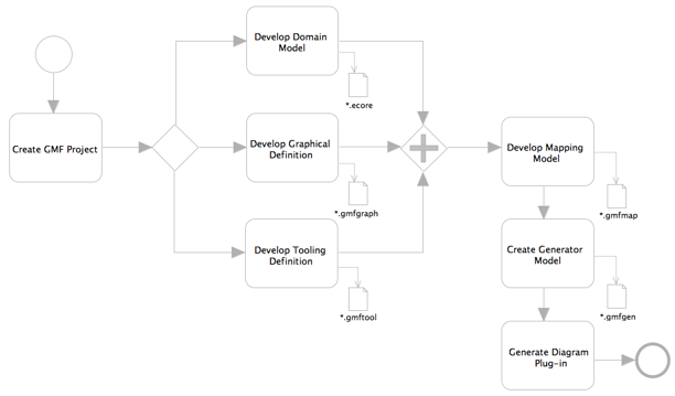
Generation framework of GMF allows users to define their custom diagram structure. Graphical definition is used to define how exactly the diagrams of their respective models look on canvas, be it like ellipse, circle, rectangle, compartments, link with arrow decorations. Tooling definition lets you define the tools that are to be presented in the palette. Here you can choose custom icons for every tool, group the tools in palette. GMF provides you with a "flyout" palette that can be collapsed or expanded as required. Domain Mapping brings together all 3 graphical definition, tooling definitions and domain model (designed using EMF). After the Mapping is over, GMF provides user with a generator model that allows implementation details to be defined for generation phase. More in detail will be posted in forthcoming chapters.
Runtime Framework:
The production of an editor plug-in based on the generator model will target a final model;
 that is, the diagram runtime (or "notation") model. The runtime is bridge between the notation and domain model(s) when a user is working with a diagram. It also provides for the persistence and synchronization of both. The runtime not only allows easier integration between EMF and GEF, but provides additional services like: transactions support, extended meta-modeling facilities, notation meta-model, variability points used for runtime extensibility of generated code, etc.
Sunday
GMF Generation Freamework
The generative framework of GMF provides the possibility to define future diagram using EMF models, and to generate code using this information. A GMF user will get all the advantages of a generative approach – fully functioning diagramming code automatically generated and easily regenerated upon model modification. Additional generator-specific variability points aid in customization of the generated code for the end-user. Generated code is optimized. As you will recognize, the generative part mostly involves working on developing a new language for describing diagrams and fits perfectly into the Generative Programming or Software Factories concepts.
GMF defines a specific numer of metamodels using Eclipse's EMF. Some of these meta-models will be instantiated during editor-generation. Eclipse has a GMF Dashboard view that will show how these metamodels are related to generate the GMF Editor. This looks pretty much like this.
The following are the metamodels used:
- Notation metamodel
- Graphical Definition Metamodel
- Tooling Definition Metamodel,
- Mapping metamodel
- Generator metamodel
You can define graphical representations and tooling before the semantic model, as all these 3 are independently developed. I will not explain the generation framework part in much detail. GMF Tutorials are pretty good enough for using these models. If possible I can provide links to the specific tutotrials for each model.
Eclipse has something called GMF Documentation Index but the index contain many repeated stuffs. I also felt that its not properly organized. There are many presentation available too. I hope this can be pretty useful to understand GMF better.
Saturday
Notational Model
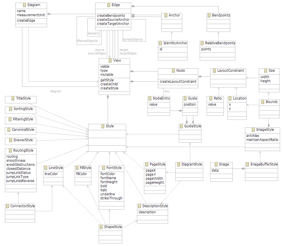
The notation model (metamodel image) is used to store visual information necessary for diagram drawing and is independent from the underlying semantic model (instantiated from EMF metamodel). For example, it is used to store the position and size of nodes, bounds of the nodes, link bend point locations, linkcolor styles, etc.
The notation model is mostly based on the following sub-classes of abstract class View: Diagram, Node and Edge. Each of these subclasses is used to store a corresponding set of properties specific for Diagram, Node or Edge visual representation, respectively. The notation model can be extended with some userdefined data by attaching specific Style to the existing View instance. Each opened diagram editor has own notation model instance attached and is actively used by the runtime as an API for storing and loading diagram-specific information.
The unifying force of GMF is the notation meta-model which provides the concrete link between the EMF and GEF. It is the scaffolding around which GMF diagram capability is built. The most important aspect about the notation meta-model is that it is completely domain independent. By having it be generic across domains, this allows the engine to behave in a common way and provide a common feature set that can be absorbed into those domains. The only link to the semantic model is a reference stored on the View element in the hierarchy. The GMF editparts always navigate to the semantic model through this reference.
Subscribe to:
Posts (Atom)
